Core Idea
A device tree is a structured hardware description passed to Linux at boot. It tells the kernel what hardware exists, how it is connected, and which resources each device needs: register addresses, bus addresses, interrupts, GPIOs, clocks, regulators, DMA ranges, pinmux choices, and graph links.
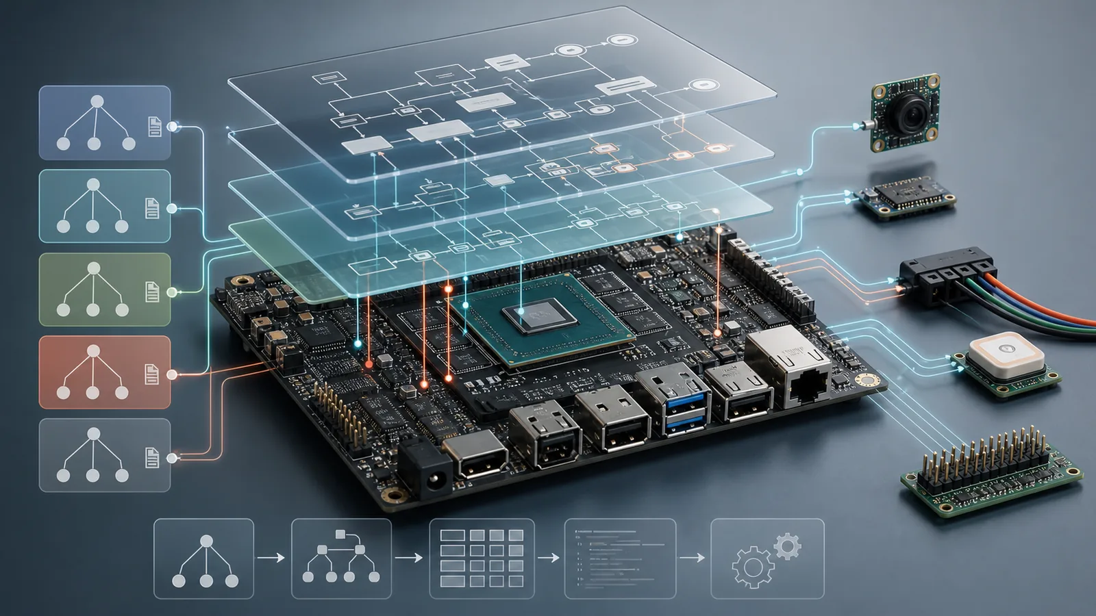
On Jetson AGX Orin, this matters because the Tegra234 SoC, P3701 module, P3737 carrier board, and optional cameras or header devices are separate layers. The kernel driver is generic; the tree says which concrete instance is present on this exact board.
Tree Structure
A device tree is made of nodes and properties. Nodes form the hierarchy.
Properties are name-value pairs inside a node. A node may describe a bus,
a controller, memory, a clock provider, a regulator, a camera sensor, an
EEPROM, or a logical grouping such as aliases.
/ {
    compatible = "nvidia,p3737-0000+p3701-0000", "nvidia,tegra234";

    aliases {
        i2c0 = &gen1_i2c;
    };

    memory@80000000 {
        device_type = "memory";
        reg = <0x0 0x80000000 0x0 0x80000000>;
    };
};

&gen1_i2c {
    status = "okay";

    eeprom@50 {
        compatible = "atmel,24c02";
        reg = <0x50>;
    };
};| Piece | Meaning |
|---|---|
/ | The root node. Top-level board identity and global nodes live here. |
node@unit-address | A child node. The text after @ usually matches the first address in reg. |
label: node { } | A source label. Other nodes can refer to it with &label. |
&gen1_i2c { } | A patch to an existing labeled node from an included .dtsi. |
property = value; | A property. The binding for that compatible string defines what it means. |
The hierarchy usually follows addressable containment. An I2C sensor is
below an I2C controller. An SPI flash is below an SPI controller. A
memory-mapped UART is below an SoC bus node. Cross-links that are not
parent-child relationships use phandles, such as &gpio,
&clock, ®ulator, or camera endpoints.
Syntax And Data
DTS syntax is small, but dense. The important trick is knowing whether a value is a string, a 32-bit cell array, bytes, a boolean property, or a phandle reference to another node.
| Form | Example | Use |
|---|---|---|
| String | status = "okay"; | Names, modes, statuses, clock names. |
| String list | compatible = "vendor,part", "fallback"; | Driver matching from most specific to most general. |
| Cells | reg = <0x50>; | 32-bit integer values. Larger values use multiple cells. |
| Phandle | clocks = <&bpmp TEGRA234_CLK_EXTPERIPH1>; | Reference to another provider node plus provider-specific cells. |
| Bytes | local-mac-address = [00 04 4b 00 00 01]; | Raw byte arrays. |
| Boolean | interrupt-controller; | True when present, false when absent. |
Common keywords and properties:
/dts-v1/;declares DTS source syntax./plugin/;marks a source file as an overlay.#includepulls in shared.dtsifiles.compatibleis the main driver-match string list.status = "okay"enables a node;"disabled"keeps it inactive.#address-cellsand#size-cellsdefine how children encodereg.rangesmaps child bus addresses into parent bus addresses.interrupt-parentandinterruptsdescribe interrupt wiring.
DTS, DTSI, DTB, DTBO
.dts: a top-level source file for a board or overlay..dtsi: an include file shared by many boards, often for the SoC, module, carrier, camera, or power tree..dtb: the compiled binary device tree loaded by firmware and handed to Linux..dtbo: a compiled overlay that patches a base tree, commonly used for optional header, camera, or carrier-board changes.
#include "tegra234.dtsi"
#include "tegra234-p3701.dtsi"
#include "tegra234-p3737.dtsi"

/ {
    model = "Custom Jetson AGX Orin board";
    compatible = "custom,agx-orin-carrier",
                 "nvidia,p3737-0000+p3701-0000",
                 "nvidia,tegra234";
};
In practice, Jetson AGX Orin device trees are layered. A board
.dts includes Tegra234 SoC files, P3701 module files,
P3737 carrier files, power-tree files, pinmux files, and optional
peripheral files.
AGX Orin Walk
Jetson AGX Orin uses the Tegra234 SoC, commonly with a P3701 module and
P3737 developer-kit carrier board. NVIDIA's public tree is split into a
lower upstream-aligned layer and an nv-platform layer that
adds platform content. The top-level AGX Orin DTBs are named around
tegra234-p3737-0000+p3701-000x-nv.dtb, where the final
module SKU changes with the exact module.
Read the file from top to bottom as layers:
- Root node: board identity,
model, top-levelcompatible, aliases, chosen boot data, memory. - SoC includes: Tegra234 controllers such as I2C, SPI, UART, PCIe, USB, CSI, GPIO, pinctrl, clocks, and interrupt controllers.
- Module includes: P3701 power rails, module pins, thermal, EEPROM, and module-specific constraints.
- Carrier includes: P3737 connector routing, GPIO usage, header functions, cameras, display, USB, PCIe, and storage routing.
- Peripheral patches: board-specific changes that enable or disable nodes and attach child devices.
/ {
    model = "NVIDIA Jetson AGX Orin Developer Kit";
    compatible = "nvidia,p3737-0000+p3701-0000", "nvidia,tegra234";

    chosen { };
    aliases { };
    memory@80000000 { };
};

&gen1_i2c {
    status = "okay";
    #address-cells = <1>;
    #size-cells = <0>;

    eeprom@50 {
        compatible = "atmel,24c02";
        reg = <0x50>;
    };
};
The important pattern is that an SoC file may define a controller as
disabled or generic, and the board file later patches it with
&label { status = "okay"; ... }; when that controller is
actually wired on the carrier.
Buses And Devices
Device tree describes a system as buses with devices below them. The parent bus decides how child addresses are interpreted.
i2c@3180000 {
    status = "okay";
    #address-cells = <1>;
    #size-cells = <0>;

    sensor@10 {
        compatible = "sony,imx219";
        reg = <0x10>;
        clocks = <&bpmp TEGRA234_CLK_EXTPERIPH1>;
        reset-gpios = <&tegra_main_gpio TEGRA234_MAIN_GPIO(H, 3) GPIO_ACTIVE_LOW>;
        avdd-supply = <&vdd_2v8_cam>;
        status = "okay";
    };
};
Here the I2C bus says child addresses use one cell and no size cell, so
reg = <0x10> means I2C address 0x10. On a
memory-mapped bus, reg usually means register base plus size.
On SPI, reg = <0> usually means chip select 0.
A camera sensor node usually needs an I2C address, external clock, reset or power GPIOs, regulators, and a graph endpoint that links it to the CSI receiver. A GPIO LED, SPI ADC, PCIe endpoint, USB port, or I2C EEPROM uses the same idea, but each one follows its own binding.
How Drivers Use It
During boot, Linux unflattens the DTB into kernel data structures. Platform
bus code, I2C core, SPI core, and other bus drivers create Linux devices
from enabled nodes. A platform, I2C, SPI, or V4L2 driver advertises an
of_device_id table. If the node's compatible
string matches, the driver's probe() runs.
static const struct of_device_id drhyme_of_match[] = {
    { .compatible = "digital-rhyme,orin-demo" },
    { }
};
MODULE_DEVICE_TABLE(of, drhyme_of_match);
Inside probe(), the driver reads properties such as
reg, interrupts, reset-gpios,
*-supply, clocks, and graph endpoints. If the
property names do not match the driver's binding, the driver may probe
but fail later, or never bind at all.
static int drhyme_probe(struct platform_device *pdev)
{
    struct device *dev = &pdev->dev;
    const char *label;

    of_property_read_string(dev->of_node, "label", &label);
    dev_info(dev, "DT label: %s\n", label);
    return 0;
}
This is why bindings matter. The binding is the contract between the DTS
author and the driver author: what compatible strings exist,
which properties are required, which are optional, and how each value is
encoded.
Compile
Device-tree source is compiled with the Device Tree Compiler,
dtc. Use -@ when building overlays because it keeps
symbols needed for fixups.
# Compile a full tree
dtc -I dts -O dtb -o tegra234-custom.dtb tegra234-custom.dts

# Compile an overlay
dtc -@ -I dts -O dtb -o jetson-orin-header-overlay.dtbo jetson-orin-header-overlay.dts

# Decompile for inspection
dtc -I dtb -O dts -o running-tree.dts /boot/dtb/kernel_tegra234-p3737-0000+p3701-0000-nv.dtb
In a Jetson Linux source tree, kernel builds usually compile DTBs as part
of the kernel device-tree target. For quick experiments, direct
dtc builds are useful, but final board support should live in
the proper Jetson kernel source tree and flash/deploy flow.
Install And Restart
A changed base .dtb normally must be installed where Jetson
firmware expects it, often under /boot/dtb/ or through the
flashing package, depending on the Jetson Linux release and boot setup.
The board must reboot before the kernel receives the new tree.
sudo cp tegra234-custom.dtb /boot/dtb/kernel_tegra234-p3737-0000+p3701-0000-nv.dtb
sudo reboot
On Jetson AGX Orin, UEFI may load the kernel DTB from an
FDT entry in /boot/extlinux/extlinux.conf. If that
entry is missing or the file is not present, UEFI can fall back to the DTB
stored in its bootloader partition. For production carrier changes, use
the NVIDIA flash flow so the expected DTB_FILE and overlay
files land in the right place.
After reboot, check the live tree exported by the kernel:
# Inspect a live property
cat /proc/device-tree/model

# Search live nodes
find /proc/device-tree -iname '*i2c*' | head

# Confirm a compatible string
tr '\0' '\n' < /proc/device-tree/path/to/node/compatibleOverlays
An overlay is a patch applied to a base device tree. On Jetson AGX Orin, overlays are useful for optional hardware: camera modules, 40-pin header changes, extra I2C/SPI devices, or carrier-board variants.
/dts-v1/;
/plugin/;

/ {
    compatible = "nvidia,p3737-0000+p3701-0000", "nvidia,tegra234";

    fragment@0 {
        target-path = "/";
        __overlay__ {
            drhyme_demo {
                compatible = "digital-rhyme,orin-demo";
                status = "okay";
            };
        };
    };
};
A target points to a label in the base tree, while
target-path points to an absolute node path. Labels are nicer,
but only work when the base tree was built with symbols.
# Build overlay with symbols
dtc -@ -I dts -O dtb -o jetson-orin-header-overlay.dtbo jetson-orin-header-overlay.dts

# Combine one overlay with a base tree for inspection
fdtoverlay -i base-agx-orin.dtb -o test-agx-orin.dtb jetson-orin-header-overlay.dtbo
NVIDIA's flash configuration can list overlays in OVERLAY_DTB_FILE.
Jetson extlinux can also name kernel-only overlays with OVERLAYS.
Either way, the kernel sees the result only after boot, so expect a reboot
after changing a DTB or DTBO.
Debug
- Use
dmesg | grep -i ofand driver-specific logs to see binding failures. - Use
ls /proc/device-treeto inspect what the kernel actually received. - Use
dtc -I dtb -O dtsto compare a compiled DTB with the source you expected. - Check
status = "okay"; disabled nodes are intentionally ignored. - Check the driver's binding document before inventing property names.
References
NVIDIA Jetson Linux Developer Guide NVIDIA Kernel Customization Jetson AGX Orin Bring-Up Linux Devicetree Documentation Linux Devicetree Bindings Devicetree Specification Basics